Sunday, December 18, 2022

1541 Drive Repair - Part 2


In my last post I began the process of repairing a Commodore 1541 disk drive. In that post I got the power on self test to pass but the drive would have some other problems that needed to be resolved. 

To continue the troubleshooting process I decided to write a test program using my IF65 in-circuit emulator. There are other ways I could have tested the drive, but I choose this options for two reason. First, I used the IF65 to do this sort of testing at my first electronics job, so there was some nostalgia for doing it this way. Second, this would give me a tool I could use to quickly troubleshoot other drives. 

The IF65 allows the 6502 code to communicate with a terminal so this made it easy to build a interactive test program. Here is a look at the menu for the test program. 


The first test was pretty simple, by pressing 'O' of 'F' on the terminal keyboard it would turn the activity LED on and off with a simple write to one of the 6522 VIAs. The motor test worked the same way to turn the spindle motor on and off. The write protect test continuously displayed the state of the write protect sensor. The last of the first batch of tests I wrote was the head test which allowed me to move the read/write head in and out. 

On the unit under test all of these tests passed except the head test, it was unable to move the head in either direction. I carefully checked the signals in the stepper drive circuit and everything looked ok, so I tried turning the motor manually and it would not move. I finally used a pair of pliers to grab the motor shaft and I able to break it loose. 

Next thing I had to deal with was a minor mechanical problem. The spring for the drive door latch was missing. I didn't have anything that was an exact fit, but I found a spring that was close and cut it shorter to fit. Initially the spring kept popping out so I had the bend the ends in a little to make a tighter fit on the pegs on either end. 


With the basic functions of the drive tested and repaired, next thing was to check the speed. The drive is designed with a very clever way to do this without needing any test software. If you look at the bottom of the drive mechanism you will see this checkboard pattern on the bottom of the spindle motor. When viewed under fluorescent lights it can be used to adjust the drive speed. Fluorescent lights strobe at whatever the AC line frequency is, so there are two tracks on that pattern, one for 60hz as found in the US and the other for 50hz found in other countries. When the speed is correct the marks on the appropriate track will appear to remain stationary. If it's running to fast or slow the pattern will slowly drift in one direction of the other. On the drive PCB there is a potentiometer that is used to adjust the speed. You turn the potentiometer until the pattern stops moving. 


With the speed adjusted I was able to boot a diagnostic disk. I used that disk to double check the speed, and finally do the head alignment. 


Monday, October 31, 2022

Commodore 1541 Drive Repair Part 1


I recently attended a repair workshop at the System Source Computer Museum in Hunt Valley Maryland. This was my first time attending one of these events so I didn't bring anything with me to work on, I figured I might find someone else that needed help, which is exactly what happened. I met someone who had brought a bunch of Commodore 1541 drives and was hoping to find someone who could help repair them. Even though I had never worked on  a 1541 drive I knew they were 6502 based to I thought I would take a crack at it. 

Most of the drives would not even get through their power on self test, indicated by the activity LED flashing. One started to emit a burning smell when we powered it up, so we put that one aside. Another would not power up at all. We swapped chips on a few but didn't make any progress that way. There was one that powered up properly but as we were trying to do further testing with it connected to a C64, the computer failed. So, we didn't make much progress there but I took one of the drives home to work on.

Before I could dig into the drive I needed some documentation. I found this site which has a good collection of schematics for various versions of the drive:

http://www.zimmers.net/anonftp/pub/cbm/schematics/drives/new/1541/index.html

I also found a couple good books on Archive.org:

Commodore 1541 Troubleshooting and Repair Guide

The Anatomy of the 1541 Disk Drive

The first thing I noticed was the C21 tantalum capacitor had burned up. This cap is between the +12V supply and ground so was probably acting as a filter cap. The +12V supply still looked good with the cap burned out so I continued to work on the drive until I was able to get a replacement. 


The next step was to troubleshoot the power on self test problem. In a previous post I talked about the IF65 in-circuit emulator that I used at a previous job. Troubleshooting this sort of failure was a perfect application for this device. I started by connecting it to a known good drive to make sure everything worked ok. 


With the IF65 setup verified I re-connected it to the unit under test. I started by testing the ROM on the bad unit, and that seemed to be ok. Next I ran a RAM test and immediately saw a failure across the whole RAM address range. The errors were pretty random so it didn't look like just a bad data or address line. Next I turned to the IF65's address trap functionality and checked out the chip enable lines which looked good. The addresses lines also looked good, but I was getting very odd signals on the data bus. 

The RAM chip on my good drive was soldered in, so swapping was not an option, so I removed all the other chips on the bad unit that were connected to the data bus, but the RAM test still failed. I started to look through my surplus chips to find an equivalent RAM chip and quickly noticed the problem. The chip in the RAM socket was actually a ROM from another drive and not a RAM chip! Not sure if this happened when we were swapping chips at the repair day or happened during a previous repair attempt. I did find an equivalent RAM chip in my collection, put that one in the drive and it passed the power on self test. 

This was not the extent of the problems with this drive, I will cover more of the repair process in my next post.


Saturday, September 24, 2022

Infotron Systems IF-65


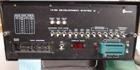
Back in the late 80's and early 90's I worked for Infotron Systems (later Gandalf Technologies) which manufactured data communications equipment. A lot of Infotron’s equipment was based on the 6502 microprocessor, so much so that they designed and manufactured their own 6502 in circuit emulator (ICE) the IF65. The IF65 was a great tool for both developing embedded 6502 software and for troubleshooting 6502 hardware. The IF65 was mainly used in house, but I know of at least one other company that Infotron sold them to. Fortunately, I ran across a working IF65 at a flea market a long time ago.


The built in monitor software is accessed through a serial terminal. The monitor provides functions to read/write memory, test RAM, assemble and disassemble code, and access the EPROM programmer.


I worked in the repair department, initially doing manufacturing repair and then eventually customer return repairs. We used the IF65 to run special test programs and as a general troubleshooting tool for 6502 based boards. This version of the IF65 has 64K of static RAM that can be configured to overlay the product's memory in 4K blocks. You would normally set this up to overlay the ROM portion of the product's memory map. Code could then be loaded by reading it from an EPROM using the EPROM programmers, downloaded from a host computer (we used VAX mainframes at Infotron), or even entered using a built in line assembler.


A really useful feature for troubleshooting was the address trap function. If, for example, you wanted to troubleshoot the address decoding hardware you would set the trap address to the address you were trying to test and then set the switches for read, write, and/or opcode access. Now any time that address is accessed you would get a sync pulse output through the connector on the lower right side. You would hook this signal to one channel of an oscilloscope and then use the other channel to probe the circuit and you would see what a signal state was as the moment the memory access was happening. 

Another feature that comes in really handy for running test software is the ability of the 6502 code to access the serial ports on the IF65. This allows the test software to interact with the user even if the unit under test is totally non-functional. This functionality, when enabled, is accessed with the 6502 BRK instruction. The byte after the BRK command contains the command you want to execute and the Accumulator is used to pass data. For example, to print a character you would do this:

LDA #$30
BRK
.BYTE #$11


Sunday, September 4, 2022

HLL65F - INDEN/UNDEN - Mystery Solved

In my previous post I talked about some mysterious code in the macro definitions for the Atari Crystal Castles arcade game source code. Someone responded to my post about this and pointed me to Franz Lanzinger who was one of the original authors of Crystal Castles who in turn pointed me to Dave Shepperd who wrote that assembler. He confirmed that this was a custom assembler developed for Atari:

"Yes, I wrote both versions of mac65. We called it macxx way back when (because it would assemble for the 6502, 65C02, 6800, 68000, and others). The first version was written in PDP11 assembly for RT11 and it used linkm as a linker, the other tool I wrote. We used those tools for a year or so after getting the VAXen. The second and current version was written in C (first DEC C for the VAX, then subsequently others and finally gcc) and compiled on various O/S. I've only been maintaining it on Linux, but it probably will still build on many others, especially those Linux like. Not sure if it would work anymore on 16 bit machines. This version uses another of my tools also written in C: LLF (Link+Locate+Format) as the linker."

He also provided an explanation of how he believes the two mystery lines worked:

.LIST SRC(...S1,1)

The .LIST pseudo op controls what get's output to the listing file. The SRC flag says to turn on the output of the assembler source code and the values in parenthesis after it control the details of the output. The first parameter tells the assembler which columns to start outputting the source on. The second value, if present and not zero, tells the assembler to wait until the next line before changing the output column instead of doing it on the current line.

.PRINT ..NST$(37,1,16,1,38'->')

The .PRINT pseudo op prints text to the listing file. The expression after .PRINT is evaluated and the result it what will be printed. Again, we have a list of parameters to control this output. This is a pretty esoteric command so I am not sure if I would have every figured this out:

37 = Column to start the print on
1 = How many characters of the value to print out 
16 = The radix of the value, in this case it will be printed as hexadecimal
1 = If present and non-zero, print the leading zeros
38=This parameters is usually used to indicate that the sign should be output, but since it has a text string after it it functions differently. In this case the text "->" will be output starting at column 38.

Let's look at the end result of all of this. Here is a chunk of source code using two nested IF macros:

IFEQ
INX
IFEQ
LDX 40
ENDIF
DEY
ENDIF

The listing output would end up looking something like this:

                                     0->
           F004  D0 FE                      BNE .
   10      F006  E8                         INX
                                     1->
           F007  D0 FE                         BNE .
   12      F009  A6 28                         LDX 40
           F008  02                            .BYTE ...S0
                                     1<-
   14      F00B  88                         DEY
           F005  06                         .BYTE ...S0
                                     0<-


Sunday, August 7, 2022

HLL65F - INDEN/UNDEN

Notes: Since writing this post I have solved the mystery of the two cryptic lines, I wrote another post about this: 

https://dansdigitalarchaeology.blogspot.com/2022/09/hll65f-indenunden-mystery-solved.html

In my last post I introduced the HLL65 high level language 6502 macro library used in the Atari Crystal Castles source code. The macro definitions used macros called INDEN and UNDEN that I assume are for handling indentation of the code in the listing file. Exactly how these work is a little but of a mystery to me. Here is the code for INDEN:

.MACRO $INDEN
.PUSH REGSAV,...S1

.IF LT,..NST$
.ERROR ..NST$ ; STACK UNDERFLOW
..NST$ = 0
.ENDC

...S1 = ..NST$+1*3+..SRC$
.IIF GT,...S1-<9.*3+..SRC$>,...S1 = 9.*3+..SRC$
.LIST SRC(...S1,1)
.PRINT ..NST$(37,1,16,1,38'->')
..NST$ = ..NST$ + 1
.POP REGSAV,...S1
.ENDM

Like most macros is starts by saving a variable on the stack. The ..NST$ variable is used to keep track of the depth of the indent, so the next block of lines checks to be sure the code hasn't undented further then it has indented and if it did it throws an assembler error. 

When the macro library is initialized ..SRC$ is set to 41, so the next line sets ...S1 to 41 + 3 times the current number of indents. The next line checks if ...S1 is beyond 9 indents and if it is, it sets it back to the value for 9 indents. 

The next line is the first one I don't understand. According to documentation I found for a VAX assembler, .LIST is used to control what gets displayed in the listing, but the documentation does not list the argument syntax used in this code. It's possible this is displaying the current line at a specific place on the line. 

The .PRINT pseudo-op is used to write text to the listing output, but the rest of this line is quite cryptic. The string '->' makes sense as an indication of indentation, but I am not sure what the numbers before it do. I also don't understand the parenthesis right after the ..NST$ variable. 

The next line increments the indent counter and finally the value of ...S1 is restored. 

The OUTDEN macro works the exact same way as this macro, but it just reduces the indent. 

If anyone has any ideas about the two cryptic lines, let me know. 


Saturday, August 6, 2022

HLL65F.MAC

HLL65F.MAC is a standard Atari macro library that adds some high-level language constructs to the 6502 assembler. It adds IF/THEN statements, conditional loops and a few other miscellaneous helper macros. Let's start by looking at an example of a conditional:

CPX #78
IFEQ
   ADC #2
ENDIF

First, keep in mind that this is not conditional assembly, there are pseudo ops for that, this is an actual runtime conditional. This macro check if the zero flag is set and if it is the code between the IFEQ and ENDIF is executed. Let's look at how these macros are expanded. First, a macro is used to define the IFEQ macro:

    DEFIF IFEQ,BNE

DEFIF is defined with this macro:

.MACRO DEFIF .1.,.2.

.NOCROSS .1.
  .MACRO .1.
IFXX .2.
.ENDM
.ENDM

It will expand to this:

.NOCROSS IFEQ
.MACRO IFEQ
    IFXX BNE
.ENDM

.NOCROSS tells the assembler not to add this symbol to the cross reference list. The rest of the expansion is the definition of a new macro which is just the IFXX macro with "bne" as the parameter. Here is the IFXX macro:

.MACRO IFXX .1.

LOC 0
.1. .
.ENDM

This expands to:


LOC 0
bne .

The first line is another macro which we will look at next. The second line branches back to itself. Since the macro is looking for Equals, this line will branch over the code in the block if the condition is Not Equals. Until the ENDIF is assembled the assembler doesn't know what the actual branch target should be, so the branch to self is used as a placeholder. Here is the LOC macro:

.MACRO LOC type
$INDEN
.PUSH REGSAV,...P0,...S0,...P1,...S1
...P0 = .
...S0 = type
.PUSH PC,...P0,...S0
.POP REGSAV,...S1,...P1,...S0,...P0
.ENDM

and here is the expansion:

$INDEN
.PUSH REGSAV,...P0,...S0,...P1,...S1
...P0 = .
...S0 = 0
.PUSH PC,...P0,...S0
.POP REGSAV,...S1,...P1,...S0,...P0

There are two possible values for the type parameter, 0 for IF blocks and 2 I believe is for a loop block but I haven't figured that one out yet. The INDEN macro is for doing indents in the listing and doesn't impact the code that is generated, I will code this macro in another post since it is a little mysterious. The second line saves a couple variables onto the REGSAV stack. ...P1 and ...S1 aren't  used so they didn't actually have to save then. Next it puts the current program counter into ...P0 and the type into ...S0 and pushes these on the PC stack, these will be used later to end the block. Finally the original variable values are restored from the stack.

Now that the block has been started we need to look at how it ends, in this case with the ENDIF macro:

.MACRO ENDIF
THEN
.ENDM

This macro is simply composed of another macro called THEN. I haven't dug into how you would use THEN by itself. THEN looks like this:

.MACRO THEN
FND
$UNDEN
.ENDM

just like $INDEN, $UNDEN is used for indentation in the list and I will cover this in another post, so that just leaves the FND macro:

.MACRO FND
.PUSH REGSAV,...P0,...S0,...P1,...S1
...P0 = .
.POP PC,...S1,...P1
.if eq,...s1&2
    . = ...P1+1
    .IF EQ,...S1&1
        ...S0 = ...P0-...P1-2
        .IIF GT,...S0-127.,.ERROR ...S0 ; BRANCH OUT OF RANGE
        .IIF LT,...S0+128.,.ERROR ...S0 ; BRANCH OUT OF RANGE
        .BYTE ...S0
    .IFF
        .WORD ...P0
    .ENDC
     . = ...P0
 .iff
     .ERROR TYPE ;inappropriate END for structure type
  .endc
 .POP REGSAV,...S1,...P1,...S0,...P0
.ENDM

This is the workhorse of this entire macro. It is basically going to use the information on the stack to modify the BNE opcode that was assembled in the IF macro so that it will branch past the block of code if the condition wasn't met. 

 First it saves that registers on the REGSAV stack so they can be restored at the end of the macro. Next the type is popped from the stack and stored in ...S1 and the program counter is popped and stored in ...P1. Next it checks if bit 1 or the type is set, in this case it will not be since the type is 0 so the condition will be met since the conditions is "equals zero". The next line will set the current program counter to the original program counter + 1 which will point it to the offset in the BNE opcode. Next bit 0 of the type is checked and again the condition is met. Next the offset for the branch is calculated by subtracting the original program counter from the program counter as it was when the macro started and then subtracting 2 and storing the result in ...S0. The next two lines check if the branch will be out of range, and if it is shows an assembler error.   After the just check is a .BYTE pseudo op that injects the new calculated offset into the BNE opcode that was assembled in the IF part of the macro. After the inner condition the current program counter is restored to where it was at the start of the macro, and then finally the registers are restored. 

These macros are a little complex but they do provide a clever way of implementing run time conditional blocks. The use of the assembler stack in the macros allows you to next IF blocks several levels deep just like in a higher level language. 


Sunday, April 24, 2022

Crystal Castles Assembler - Stacks

This is a continuing look at some of the features of the 6502 assembler Atari used for arcade games like Crystal Castles. One of the unique features, one I haven't seen in any other 6502 assembler, is the ability to define assembler level stacks. These have nothing to do with the 6502 stack, but instead are used to control the assembly process. 

You start by defining a stack using this pseudo op:

.DEFSTACK REGSAV, 4

There are two parameters. The first, in this case "REGSAV", is the name you want to give to the stack. You will use this to interact with the stack.

The second parameters, 4, is the size of the stack, so this stack will be able to hold up to 4 values.

To put a value on the stack you use the .PUSH pseudo op:

.PUSH REGSAV,1

This will push the value 1 onto the stack named REGSAV. The second parameter can also be an expression. I don't know if the original assembler allowed text strings to be pushed onto the stack but my version of the assembler only allows numbers to be pushed onto the stack. 

To get a value off the stack you use the .POP pseudo op:

.POP REGSAV,S1

This will pull the top value off the stack named REGSAV and put it into variable S1. The second parameter here must be a variable, not an expression.

You can use the .GETPOINTER pseudo op to get the stack pointer for a specific stack:

.GETPOINTER REGSAV,P1

This will put the stack pointer for stack REGSAV into variable P1. The stack pointer works from high to low, so if you declare a stack with the size 4, the initial pointer will be 4. If the pointer is 0 it means that stack is full.

Since I can only go by the source code I don't know what happens if you try to push a value onto a full stack or pull a value from an empty one. My version of the assembler currently doesn't handle these scenarios.

In a later post I will show how this features is used in the Crystal Castles source.


Sunday, April 3, 2022

Crystal Castles Assembler

When I found the Crystal Castles Source code I thought it would be cool to able to re-assemble the source so modifications could be made to the game from the original source. I didn't take long to realize that the assembler used by Atari had a lot of differences from assemblers I was familiar with. I started Googling some of the unusual pseudo ops in the source to see if I could identify an assembler that was compatible with this code. I found manuals for similar assemblers but nothing was a perfect match.

The best resource I found was the VAX MACRO and Instruction Set Reference Manual:

https://www.ece.lsu.edu/ee4720/doc/vax.pdf

It is not surprising that this assembler is close, Atari did a lot of their arcade development on DEC VAX mainframes. This became my go-to document for writing my assembler. If there was anything that was not clear from the source, but was answered in this document, I used what was in this document. 


Addressing Modes

One of the strangest differences between this assembler and other common 6502 assemblers is the syntax to define addressing modes. All the modes can be defined with prefixes to the operand, so for example, for absolute X you would do LDA AX,$1000 instead of LDA $1000,X. There are even multiple ways to define the same mode, at it appears different programmers used different ones. Here are the prefixes for the addressing modes:

# or I, - Indirect
ZX, - Explicit zero page X
ZY, - Explicit zero page Y
Z, - Explicit Zero page   
NX, - Indirect X
NY, - Indirect Y
AX, - Absolute X
AY, - Absolute Y
A, - Absolute
X, - Absolute or Zero Page X determined by the assembler 
Y, - Absolute or Zero Page Y determined by the assembler 

There are also two suffixes that can be used, (X) and (Y). You would think that these would be for indirect modes, but they are not, they are for absolute X and Y. I also found "(X" in the code. I assume this is an anomaly of the assembler where it doesn't parse the entire addressing mode identifier. 

Radix

The Atari assembler provides two different ways of controlling the radix (base) of numbers. First, the radix can be specified using a prefix on the number ^H for Hex and ^B for Binary. There is probably a prefix for octal but the Crystal Castles code doesn't use it. The second way of specifying radix is to use the .RADIX pseudo op which specifies the default radix to use when parsing numbers. For example if this is in the source:

.RADIX 16 

it will set the default radix to hex so that if a number doesn't have an explicit radix prefix it will be interpreted as hex. To avoid confusion with symbols, a hex number must start with a number if it doesn't have a prefix, so for example A5 would have to be written as 0A5. In my version of the assembler I always treat the parameter for the radix pseudo op as a decimal.

.REPT/.ENDR

The .REPT pseudo op looks pretty straight forward but there turned out to be some tricky parts to it. This pseudo-op repeats a block of code a specified number of times during assembly. It is passed one parameter which is the number of times to repeat it. 

The first interesting thing I found about it is that the Crystal Castles sources often uses it with a repeat count of zero. The basically works like a block comment, preventing the block of code from being assembled at all. 

The other interesting thing I found in the code was the .REPT blocks were sometimes ended using .ENDM, which ends a macro definition, instead of .ENDR. My theory on this is that if a repeat block is started inside a macro definition then it would make no sense for it to extend beyond the end of the definition, so it's possible that the assembler explicitly ends open repeat blocks at the end of a macro definition. This was probably an un-intended side effect of the way the assembler was written. 

I will cover some more differences in a latter post.


Saturday, March 19, 2022

Crystal Castles Source Files

In my last post I gave an overview of the files in the Historical Source Code  repository for Atari's Crystal Castles arcade game. In this post I will go into the files in detail. Here are the files in alphabetical order:

C00.DAT - C33.DAT : These contain the level data. I will go into these in more detail in a later post.

BITPAT.MAC: This files contains 8 bytes, represented as binary numbers in the file. The file is included into CEL.MAC and appears between two subroutines. It doesn't appear that this data is actually used by the game. It might be some sort of security or anti-piracy protection.

C99.MAC: Links together all the level data. This is assembled separately from the main program and becomes the second bank of ROMs.

CAL.MAC: Handles the display of the score and the high score screen.

CATOUT.MAC: Displays the Atari Easter egg message. Shown on the next level after you have jumped 128 times on the previous level.

CCN.MAC: 650X 'Universal' coin routine. This is a standard code library for handling the coin mechanism.

CCT.MAC: Draws the levels

CCUBE.MAC: Draws a cube on the screen. This is only used by the special display that happens when you score over 700,000 points.

CDB.MAC:  Routine to transfer level data from ROM to RAM 

CEE.MAC: EEROM routines 

CEEDEF.MAC: definitions for EEROM routines

CEL.MAC: Elevator handling 

CEN.MAC: Main game logic

CET.MAC: Auxiliary EEROM information, tables, output routines etc.

CG.MAC:  Global definitions and memory allocation

CGR.MAC: Global data and routines

CIN.MAC: Interrupt handlers

CLS.MAC: Sound and music data

CMAC.MAC: A couple macros to simplify common 6502 tasks

CMN.MAC: Main loop

CMR.MAC: Message display routines

CMS.MAC: Word data

CMTB.MAC: Message table

CRF.MAC: Root file

CRP.MAC: RPM (Rusty's POKEY Music) Driver

CSL.MAC: Symbol shape data

CSS.MAC: Test menu

CST.MAC: Self test

CSTART.MAC: Includes macros and zero page definitions

CWV.MAC: Level handling

HLL65F.MAC: High level language macros

M6502.MAC:  6502 general purpose macros


CJTB.MAC: This file is missing from the archive but is included in CRP.MAC. It it a patch to the POKEY music driver. I recreated this file from the original ROMs.

Thursday, March 10, 2022

Crystal Castles Source File Overview

Recently Historical Source Code published the original source code for a couple Atari arcade games including Crystal Castles. In this post I will give an overview of the the files that are included in the archive. The files can be found here:

 https://github.com/historicalsource/crystal-castles

The archive contains three sets of files for Crystal Castles, the one in the root directory of the repository, which I will call the master set, and two others sets called version-2 and version-3. In this post I will focus on the master set, since the other two contain some different files. Using my assembler I was able to re-assemble the master set to produce the ROMs that match the MAME ccastles1 set. I still need to determine if the other two versions of the source match up with other MAME ROM sets. The main ROM set in MAME, ccastles, does not match any of the source in the archive. The first ROM has a copyright message in it and the MAME base set also contains the phrase "PIRATES BEWARE" which is not in any of the source. 

Here is an overview of the files in the archive:

372X1.DOC 

This appears to be some sort of standard form used by Atari to document game projects, since similar files appear in the repositories for other games. The file contains all the details of the ROMs that make up the game, a description of how to assemble the files and a signoff form at the bottom.

022X1.DAT

This contains a single line of ASCII data that provides details of the ROMs that make up the game. This file is referenced in 372X1.DOC and is called the "Verification control file". I still need to study this file some more to understand the format.

372BR.RS4

This file is referenced in 372X1.DOC and 022X1.DAT so has something to do with the verification process, but I am not sure what the data in it represents.

*.MAC

The .MAC files are the macro-assembler source files for the game. Most of the files are for the fixed ROM and the first ROM bank. C99.MAC and the .DAT files are for the second ROM bank. CRF.MAC is the root file, the other files are either included in CRF.MAC, or included into other includes. There was one file missing from the archive, CJTB.MAC, which is included into CRP.MAC. To be able to re-assemble the code I had to re-create this file from existing ROMs. I will look at these in more detail in a future post.

Cxx.DAT

These files contain the level data for the game and are included into C99.MAC. This is assembled separately and forms the second bank of ROM.

*.LDA

These are the binary output of the original assembler in a format that makes them linkable to other binaries to form the final output. I need to do some more research to figure out the format of these files. 


Saturday, March 5, 2022

Crystal Castles Source Code


I recently ran across a bunch of Atari arcade source code that was added to the Historical Source Github site, including the source for one of my favorite games, Crystal Castles.


https://github.com/historicalsource/crystal-castles


I thought it would be cool to be able to re-assemble this back into the original ROMs. I started by trying to find an existing assembler that could do this, but the assembler used for this source had a lot of syntactical differences and features I couldn't find in any other 6502 assembler. I assume Atari used a VAX based assembler and I did even find documentation for a VAX assembler with similar features, but still not an exact match. 


I then thought about manually modifying the source to work with an existing assembler. I quickly realized that this wasn't feasible due to some of the odd syntax in this assembler. For example the Atari assembler has an different syntax for addressing modes. You can write Zero Page X like this: "LDA ZX,$PSTSL", you couldn't fix this with a simple search and replace. This would also have to be done for every game I wanted to re-assemble. 


So I decided the best option was to build my own assembler that could handle these files with little changes to the original source. The assembler I build is now able to reassemble the main source from the historical source repository and reproduce the MAME ccastles1 ROM set. 


I have setup a GitHub repository to hold the C# source code for my assembler as well as tool to split the output into separate ROMs and handle the checksum process. There is also a folder there with the files and instructions needed to rebuild the source. There are some small changes needed to the source which I have documented in the instructions, and there was one file missing from the Historical Source archive which I re-created from the original ROMs. 


https://github.com/danlb2000/AT6502


Sunday, January 23, 2022

IMSAI 8080 Introduction


A while back I acquired and IMSAI 8080 system that was headed for the trash. Many people may remember this system from the 1983 film Wargames, a personal favorite of mine. Here is a brief look at the components that came with the system, I will write some more in-depth posts on each part in the future. 


The system was in cosmetically good shape when I got it, still needed some cleaning in this picture. It powered up ok, but had some problems with the front panel that I needed to troubleshoot.


Here is a look inside. The boards there were included, front to back...

- CPU board with a Dutronics Dz80 upgrade that replaced the 8080 CPU with a Z80.
- Fully populated Z16, 16K RAM board
- Second Z16 with only 12K of RAM
- Floppy disk controller. I couldn't find any information on this one so had to reverse engineer it.
- Technical Design Labs SMB  System Monitor Board. 


Heathkit H19 dump terminal. This worked perfectly when I got it.


Innovex 10" floppy drive. I haven't tried to get this working yet.


This is a dot matrix printer that prints onto cash register style tape. There weren't any markings on it to identify the manufacturer, but I got a response from Lee Felsenstein on Facebook identify the manufacturer as  Practical Automation.